
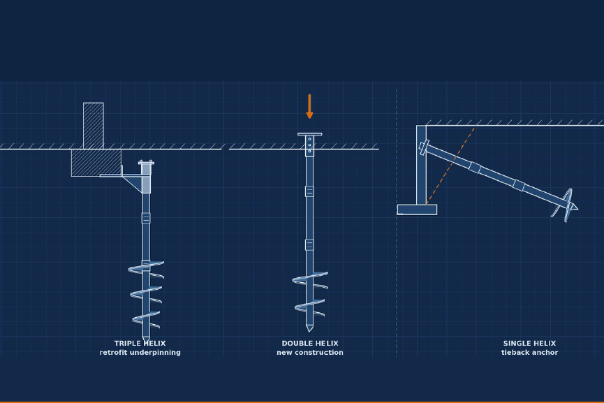
Helical piles install fast, quiet, and vibration-free with small equipment, reach limited-access sites, and are the only deep foundation whose design capacity is routinely accepted from an installation-torque correlation written into code. They lose to micropiles and drilled shafts in gravel, cobbles, very dense soil, and aggressive soils.
That summary is deliberately two-sided, because a helical pile article that only lists advantages is useless to the person who signs the drawings. Helicals are an excellent tool inside their envelope and a poor one outside it, and the boundary is sharper than most marketing suggests.
TMG Manufacturing sits on both sides of this. We build the rigs that collect the subsurface data — SPT, coring, CPT and DMT push rigs — and we manufacture the helical piles, underpinning brackets, pin piles, drill-in piles, and micropile products designed from that data. When a boring log says a helical is the wrong answer, we are the ones selling the alternative. That is why the “cons” section is the longer one.
How a Helical Pile Carries Load
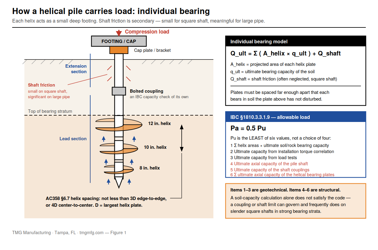
A helical pile is a steel shaft with one or more helix-shaped bearing plates welded to it, rotated into the ground by a hydraulic torque motor. Each helix advances roughly one pitch per revolution — about 3 inches — so the pile screws in rather than displacing soil laterally the way a driven pile does.
Load transfers two ways. The dominant mechanism is individual bearing: each plate acts as a small deep footing, and geotechnical capacity is the sum of the plates’ bearing capacities. The secondary mechanism is shaft friction — small for a square shaft, meaningful for large pipe. In tension the same helices work in uplift, which is why helicals dominate the tieback and guy anchor market.
Configurations and Shaft Sizes
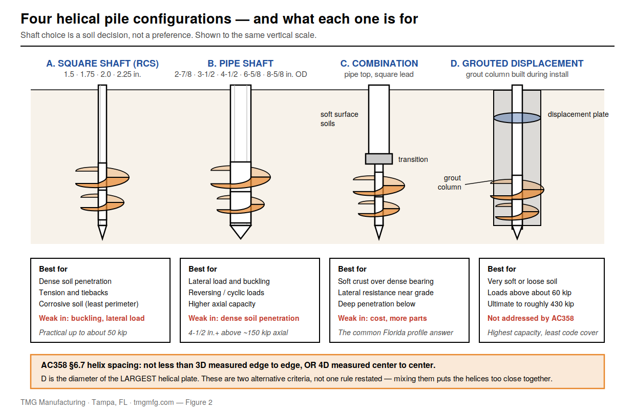
- Square shaft (round-corner square, “RCS”). 1.5, 1.75, 2.0, and 2.25 in. Highest torque capacity per pound of steel, least soil disturbance, least perimeter exposed to corrosion, best penetration into dense soil. Weak in buckling and lateral load. Manufacturer guidance puts the practical sweet spot at working loads up to roughly 50 kips.
- Pipe shaft. 2⅞, 3½, 4½, 6⅝, and 8⅝ in. OD. Far better lateral and buckling resistance, more shaft friction, more capacity — manufacturers recommend the 4½ in. and larger line for axial loads above about 150 kips and lateral loads above about 5 kips.
- Combination. Pipe on top for lateral and buckling resistance, square lead for penetration. Common where soft surface soils overlie a dense bearing stratum.
- Grouted displacement pile. A displacement plate builds a grout column around the shaft as it advances. Manufacturer literature reaches into the 400-kip ultimate range, and it is the standard answer in very soft or loose soil where an ungrouted shaft would buckle.
Helix plates are spaced so each bears in relatively undisturbed soil. ICC-ES AC358 §6.7 states the rule as not less than 3D edge to edge, or 4D center to center, where D is the diameter of the largest helical plate. Those are two alternative criteria, not one rule restated — mixing them puts your helices too close together.
The Pros and Cons, Side by Side
| Factor | Helical pile | Honest assessment |
|---|---|---|
| Installation speed | Piles per hour, not per day; immediate loading | Real advantage; often decides schedule-driven repairs |
| Installed cost | Low, in the right soil | Disappears fast in dense or gravelly soil where installation stalls |
| Vibration | Effectively none | Real advantage next to sensitive or historic structures |
| Noise | Hydraulic motor only; no impact | Real advantage in occupied buildings and residential work |
| Equipment size | Mini excavator, skid steer, or handheld | Often the only option in a basement or crawlspace |
| Capacity verification | Torque correlates to capacity | Unusual among deep foundations — but conditional and size-limited |
| Spoil generation | None | Advantage on contaminated or landfill sites |
| Tension capacity | Excellent | Best-in-class for uplift and tiebacks |
| Weather / groundwater | Installs saturated; no dewatering, no curing | Advantage in Florida-type conditions |
| Dense sand, gravel, cobbles | Poor | Stalls or grinds; often a hard stop |
| High-capacity loads | Limited on common shaft sizes | Torque verification drops out of AC358 scope on the largest shafts |
| Aggressive soils | Poor without design attention | 50-year sacrificial basis; excluded outright below 1,000 ohm-cm |
| Buckling in very soft soil | Poor for slender shafts | Below about N = 4, buckling governs, not bearing |
| Public design guidance | Thin | No dedicated FHWA manual, no dedicated AASHTO LRFD section |
Torque Correlation: The Advantage Nobody Else Has
Rotate a helical pile into the ground and the torque required to keep it turning is measured continuously by the installing equipment. That torque correlates to capacity:
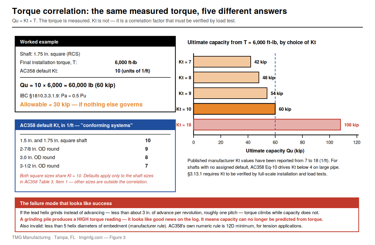
Qu = Kt × T
where Qu is ultimate capacity, T is final installation torque, and Kt is a torque correlation factor in ft⁻¹. AC358 publishes defaults for “conforming systems”: 10 ft⁻¹ for both 1.5 in. and 1.75 in. square shaft, 9 ft⁻¹ for 2⅞ in. round, 8 ft⁻¹ for 3.0 in. round, 7 ft⁻¹ for 3½ in. round.
Very few deep foundations give you this. A drilled shaft gives you an integrity test, not a capacity, until you load-test it. Driven piles give dynamic formulas and PDA. A helical tells you at every location whether it reached the torque the design assumed — before the structure goes on it.
The Part Nobody Tells You: When Torque Correlation Lies
The defaults are not universal, and it is not “just use 10.” AC358 §3.13.1 requires Kt to be verified by full-scale field installation and load tests, and the published defaults still carry a verification testing schedule. They attach to specific shaft sizes only. For sizes without an assigned default, AC358 gives Kt = 22.285 (d_eff)^−0.9195, which drives Kt down sharply as the shaft grows — around 8.5 for a 2.0 in. square shaft and below 4 for large-diameter pipe. And the criteria are explicit that the correlation “applies only to shaft sizes described in Item 1 of Table 3. For shaft sizes that are outside of this prescribed range, this torque correlation is outside the scope of this criteria.” The high-capacity pipe configurations people reach for on big projects are precisely the ones where the torque-verification advantage loses its ICC-ES standing. No brochure says that.
It inverts when the helix grinds. If the lead helix hits a hard layer and advances substantially less than its pitch — under about 3 inches per revolution — torque climbs while capacity does not. Published guidance is blunt: grinding does not mean the pile will not carry its rated load; it means capacity can no longer be predicted from torque. This is the failure mode that matters most, because it produces a high torque reading, which looks like good news on the log.
It is invalid at shallow embedment. Manufacturer guidance requires the uppermost helix at least 5 helix diameters below grade in cohesive and fine granular soils. That 5D rule is a manufacturer rule, not code and not AC358 — AC358’s own numeric rule is 12D for tension applications, with anything shallower requiring a registered design professional to set the depth.
It is calibrated on clay. Kt = 10 performs well in cohesive soils and tends to be conservative in clean granular soils. In sand it may leave capacity on the table; in a soil the correlation was never calibrated for, it may do the opposite.
One citation warning. A frequently referenced ASCE Journal of Performance of Constructed Facilities paper on installation torque and axial capacity in cohesionless soils has been retracted by ASCE, and is still cited widely without any retraction notice. If a design basis on your desk rests on it, check the source.
What the Code Actually Requires
IBC §1810.3.3.1.9 governs helical pile allowable capacity, with the same section number in the 2021 and 2024 IBC. It is routinely described online as “four methods.” It is not. It sets Pa = 0.5 Pu (Equation 18-4), where Pu is the least of six values: (1) sum of helix plate areas × ultimate soil or rock bearing capacity; (2) ultimate capacity from well-documented correlations with installation torque; (3) ultimate capacity from load tests; (4) ultimate axial capacity of the pile shaft; (5) ultimate capacity of the shaft couplings; (6) sum of the ultimate axial capacity of the helical bearing plates. Items 1–3 are geotechnical, 4–6 structural, and 0.5 is a blanket factor of safety of 2 on whichever governs.
IBC §1810.3.1.5, the design-conditions provision for helical piles, is one sentence and imposes no helix geometry: helical piles “shall be designed and manufactured in accordance with accepted engineering practice to resist all stresses induced by installation into the ground and service loads.” Note the second half — installation stresses are a code requirement, not an afterthought. Helix spacing and geometry rules come from AC358 or a manufacturer, not from that section.
IBC §1810.4.11 requires a registered design professional to set embedment depth and torsional resistance criteria, and prohibits exceeding the pile’s maximum allowable installation torque. IBC §1705.9 requires continuous special inspection during installation — equipment, pile dimensions, tip elevations, final depth, final torque. It is a standalone section, not a row in a Table 1705 matrix, and was §1704.10 in the 2009 IBC.
AC358 (24), published April 2025, is the current acceptance criteria as of August 2026. It covers axial compression, axial tension, and lateral loads, and permits Seismic Design Categories D through F where §3.14 is satisfied — older evaluation reports limiting use to SDC A, B and C are still circulating, so check the specific ESR.
Florida. The Florida Building Code, 8th Edition (2023), based on the 2021 IBC, took effect December 31, 2023; the 9th Edition (2026) is scheduled for December 31, 2026. Florida adopts IBC Chapter 18 with state amendments, and Chapter 18 carries a separate High-Velocity Hurricane Zone block for Miami-Dade and Broward with its own pile load test provisions. Do not assume the model IBC text governs on a Florida project — check §1810 and the HVHZ sections against the FBC itself.
Two things an evaluation report does not do: it is explicitly not an endorsement, carries no warranty, and still requires project-specific calculations and drawings by a registered design professional. “ICC approved” is not a design.
Where Helical Piles Are the Wrong Choice
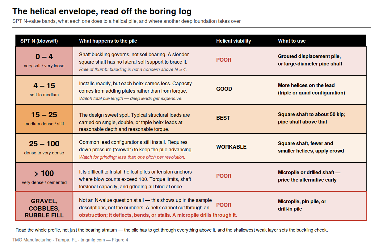
Dense and gravelly soils. Pack’s Practical Design and Inspection Guide for Helical Piles and Helical Tension Anchors puts routine installation at SPT N up to about 100 and says plainly that it is difficult above N = 100. Cobbles, boulders, and construction debris are worse than dense sand: a helix cannot cut an obstruction — it deflects, bends, or stalls. A micropile drills through what stops a helix.
Very soft soils, for slender shafts. Manufacturer guidance treats buckling as not a concern where SPT N exceeds about 4 along the full shaft. Below that, shaft buckling — not soil bearing — governs, and you need larger pipe or a grouted displacement pile.
High-capacity loads on common shaft sizes. Manufacturer-published ultimate capacities for solid square shafts run about 70 kips at 1.5 in., 100 at 1.75 in., 150 at 2.0 in., and 200 at 2.25 in.; allowable design load is half the governing ultimate per Equation 18-4. Large pipe and grouted displacement piles go higher, into the 400-kip range in manufacturer literature — but AC358 provides no design or acceptance provisions for grouted-shaft or displacement-plate piles, and the torque correlation drops out of scope on the largest shafts. The highest-capacity products in this category have the thinnest acceptance-criteria coverage.
Aggressive soils. AC358 puts helical piles outside the scope of an evaluation report where resistivity is below 1,000 ohm-cm, pH is below 5.5, sulfates exceed 1,000 ppm, or the soil has high organic content, is landfill, or is mine waste. AC358 sets no chloride limit — anyone quoting one is quoting something else.
Compare that to the FHWA/AASHTO electrochemical criteria for steel soil reinforcement in MSE walls (FHWA-NHI-09-087): resistivity above 3,000 ohm-cm, pH between 5 and 10, chlorides under 100 ppm, sulfates under 200 ppm, organics under 1 percent. FHWA is roughly three times stricter on resistivity and five times on sulfates. A soil comfortably “in scope” for an ESR would be rejected outright as aggressive backfill under those criteria.
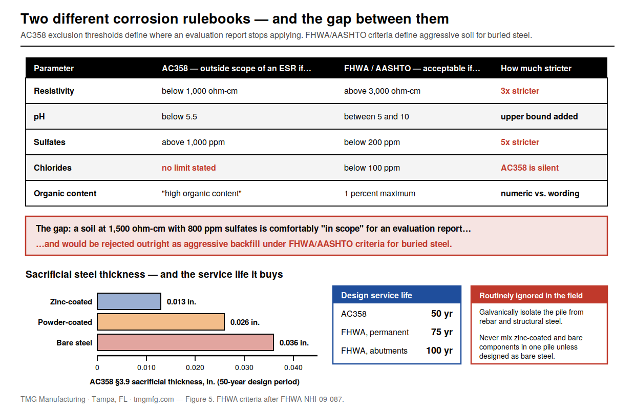
And the service life assumption is shorter than people think. AC358 §3.9 computes sacrificial thickness for a 50-year design period — 0.013 in. zinc-coated, 0.026 in. powder-coated, 0.036 in. bare steel. Read the powder-coated number carefully: the formula credits the coating with only 16 years, after which the steel corrodes as if bare. FHWA/AASHTO assume 75 years for permanent structures and 100 for abutments. An ESR-based helical pile is not designed to bridge-infrastructure service life, and nothing on the submittal says so.
Two provisions get ignored in the field: AC358 §3.9 requires components to be galvanically isolated from reinforcing steel, structural steel, and other building metals; and evaluation reports prohibit mixing zinc-coated and bare steel components in one system unless the whole assembly is designed as bare steel. A galvanized lead with bare extensions voids the corrosion basis.
Finally, the guidance gap. There is no dedicated FHWA design manual for helical piles and no dedicated AASHTO LRFD design section — FHWA NHI-05-039 is a micropile manual. Helical code standing rests on IBC §1810.3.3.1.9 plus proprietary evaluation reports. Compared with driven piles, drilled shafts, and micropiles, that is a real difference in how much of the design basis is independently reviewable.
How to Actually Choose
- Read the N-value profile through the full design depth. Long stretches under about N = 4 mean buckling territory — go to pipe or displacement. N above 100 in the bearing stratum, or anywhere you must penetrate, means installation problems: price a micropile alternative now.
- Look for gravel, cobbles, rubble, and fill in the sample descriptions. These never show up as a single number. They show up in the driller’s log — one more reason the log has to be written properly.
- Order corrosion testing where it matters. Resistivity, pH, sulfates, chlorides, organics. It is inexpensive, and it is the difference between a 50-year foundation and a warranty claim.
- Set the load-test program before installation. ASTM D1143/D1143M-26 (static axial compression) and D3689/D3689M-25 (static axial tension) are current. Always cite the dual designation; the legacy standalone “D1143” is no longer current.
- Confirm the specific ESR, not the category. Kt values, seismic design category limits, shaft sizes inside the torque-correlation scope, and corrosion exclusions are all product-specific.
For a first-pass estimate from torque and shaft type, our helical pier load calculator will get you in the right range before you commit to a configuration.
Working through a helical pile decision? TMG Manufacturing manufactures helical piles, underpinning and foundation repair products, pin piles, drill-in piles, and compaction grouting products — and we build the SPT, CPT, and coring rigs that produce the data you need to size them. If the answer is a micropile, we will tell you. Call (813) 464-2299 or toll-free 1-888-508-RIGS, or email info@tmgmfg.com.
Ramzy Moumneh, TMG Manufacturing
Frequently Asked Questions
What are the disadvantages of helical piles?
Difficult or impossible installation in dense soil, gravel, cobbles, and rubble fill; corrosion vulnerability in aggressive soils, with evaluation reports excluding soils below 1,000 ohm-cm resistivity, below pH 5.5, or above 1,000 ppm sulfates; buckling risk in very soft soil below about SPT N = 4; a torque correlation that becomes invalid when the helix grinds, and that AC358 limits to a defined range of shaft sizes; and thinner public design guidance than micropiles or drilled shafts.
How long do helical piles last?
AC358 computes sacrificial steel thickness on a 50-year design period, so an evaluation-report-based helical pile is nominally a 50-year foundation in non-aggressive soil. With galvanizing and adequate shaft thickness it can last considerably longer, but that is a project-specific corrosion analysis, not a default. FHWA/AASHTO use 75 to 100 years for buried steel reinforcement in permanent structures.
Do helical piles need a load test?
Often not, subject to the authority having jurisdiction. IBC §1810.3.3.1.9 allows ultimate capacity to be established from well-documented correlations with installation torque, which is why torque verification substitutes for load testing on many projects. But AC358 requires Kt itself to have been verified by full-scale load tests, some jurisdictions require testing regardless, and a load test is the right call on unusual soils, high-capacity piles, shaft sizes outside the AC358 range, or any site where the helix grinds.
How much weight can a helical pile hold?
Manufacturer-published ultimate capacities run roughly 70 kips for a 1.5 in. square shaft, 100 kips at 1.75 in., 150 kips at 2.0 in., and 200 kips at 2.25 in.; large pipe and grouted displacement piles reach into the 400-kip range in manufacturer literature. Allowable design load is half the governing ultimate per Equation 18-4 — so a 200-kip ultimate is a 100-kip allowable at best, often less once shaft, couplings, and helix plates are checked.
Are helical piles better than push piers?
They solve different problems. Helical piles are torqued to a target and verified from torque without any structural reaction, so they work on new construction, light structures, and in tension. Push piers are hydraulically driven using the building’s own weight as reaction, so they need a heavy enough structure — and give you a structural load test as a byproduct. On a light residential structure, push piers may not have enough reaction to reach competent bearing; on a heavy structure over deep soft soil, they often will.
Leave a Reply