Helical Pile Load Calculator
Live results update as you type. Quick screening for helical pile sizing — cohesive-soil method.
1 · Load & Safety
Enter the working (allowable) load in kips.
2 · Shaft & Helix Configuration
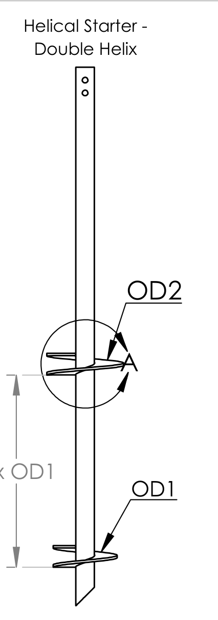
Tip: helices normally step up in size from the tip (e.g. 10"–12"–14").
3 · Project Info (for the printout)
Helical Pile Load Calculation
| Project | — |
| Address / city | — |
| Date | — |
| Shaft | — |
| Helix configuration | — |
| Required loads | — |
| Factor of safety | — |
Required installation torque
— ft-lb
Min. soil blow count required
N = —
blows/ft (SPT)
Allowable capacity
— kips
Ultimate — kips (÷ FS)
Details
| Required loads (comp / tension) | — |
| Working load × FS | — × — |
| Torque factor Kt (ICC-ES AC358) | — /ft |
| Helix bearing area, total | — ft² |
| Minimum soil blow count (N) required | — |
| Implied soil cohesion (su ≈ 125·N) | — psf |
| Project | — |
Qult = P × FS—
T = Qult ÷ Kt—
Ttension = (Pt ÷ 0.90) × FS ÷ Kt (uplift = 90% of compression capacity, Perko 2009)—
Ah = π⁄4 · (D² − d²) ⁄ 144 (per helix)—
Nreq = 8 · Qult ⁄ (9 · 1000 · ΣAh)—
su = 125 · N—
Qult = Nc · su · ΣAh (Nc = 9, bearing check)—
Qallow = Qult ÷ FS—
Bearing model: Qult = Nc · su · ΣAh with Nc = 9 (cohesive soils). P in kips is converted to pounds (×1000) for torque and soil checks.
Assumptions: cohesive-soil quick screen — bearing on helix plates only, no shaft friction, no depth or groundwater effects, torque per ICC-ES AC358 default Kt for round shaft. This is a preliminary screening tool, not an engineered design. Final designs must be reviewed and sealed by a licensed Professional Engineer.