
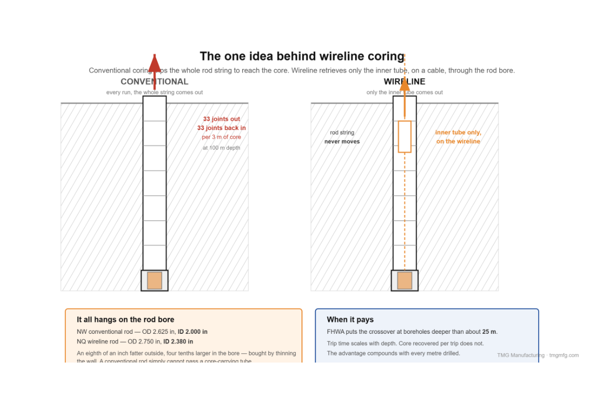
Wireline coring retrieves the core sample without pulling the drill string. The inner tube sits inside the rotating outer barrel on a bearing, holding still while the bit cuts. At the end of a run, an overshot drops down the rod bore on a cable, latches the inner tube, and winches it out. The rods never move.
That is the entire innovation. The system was patented in the early 1950s and in commercial use by the late 1950s. Everything else — the latch mechanism, the shut-off valves, the size designations — exists to make that one idea work reliably a thousand feet down.
We build SPT and coring rigs and supply wireline systems, so this is written from the equipment side: what each part does, what it sounds like when it goes wrong, and where the industry’s standards currently have a hole in them.
The problem wireline solves
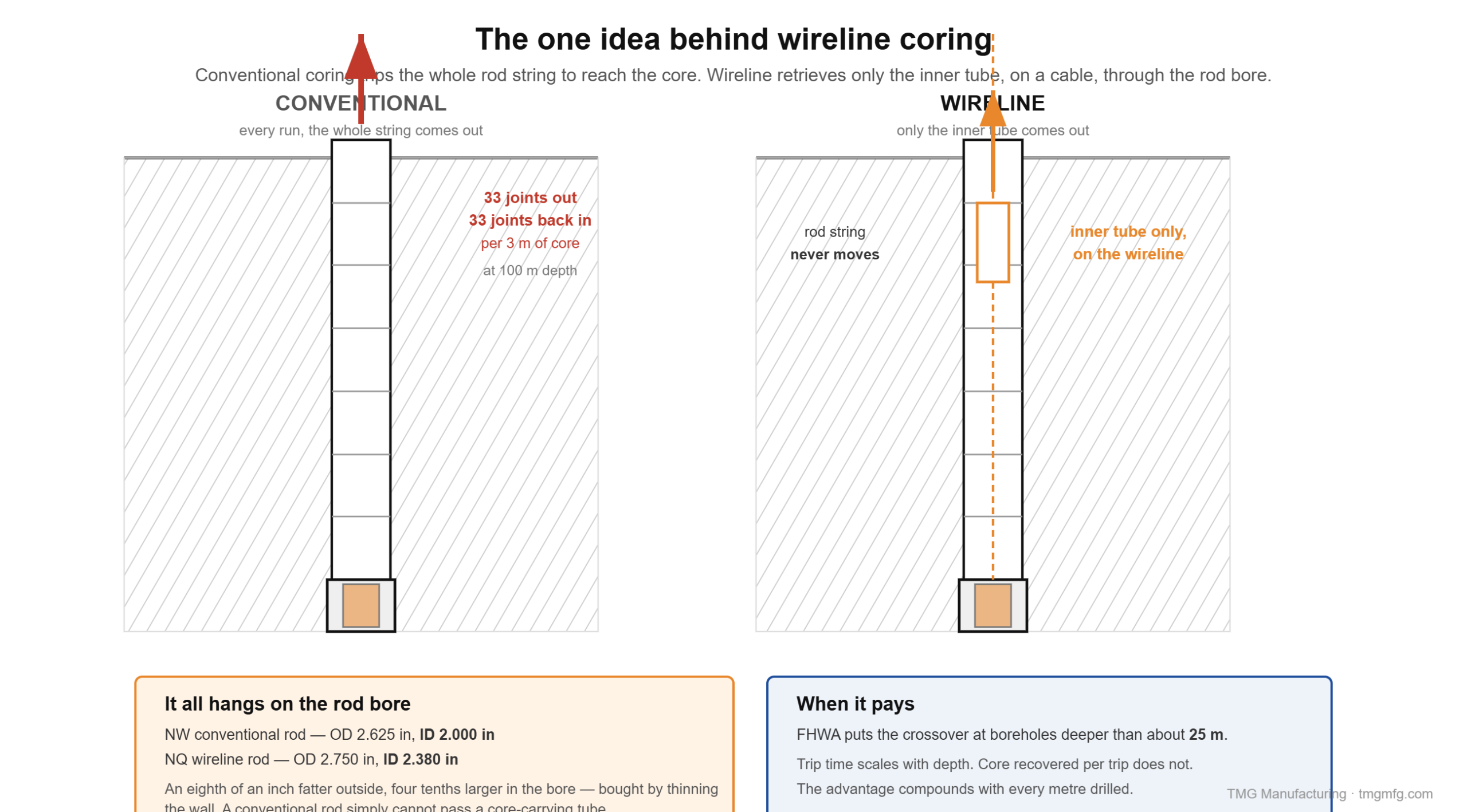
In conventional coring, the core barrel is fixed to the bottom of the rod string. To get the core, you trip the whole string — rod by rod — then run it all back in. Trip time scales with depth. Core recovered per trip does not.
At 100 meters with 3-meter rods, that is 33 joints broken out and 33 remade to recover 3 meters of core. At a brisk 30 seconds per joint each way, roughly 33 minutes of pure rod handling. At 200 meters it is 66 minutes. (That arithmetic is ours, not a published figure.)
In wireline coring, only the inner tube comes up. FHWA puts the crossover where wireline becomes economical at boreholes deeper than about 25 meters.
The whole design hangs on one dimension:
| Rod | Outside diameter | Inside diameter |
|---|---|---|
| NW (conventional) | 2.625 in | 2.000 in |
| NQ (wireline) | 2.750 in | 2.380 in |
The NQ rod is an eighth of an inch fatter outside but nearly four tenths larger in the bore, bought by thinning the wall. That bore is what an inner tube and an overshot have to pass through. A conventional NW rod cannot pass a core-carrying tube — which is why “enlarged inside diameter” is in the definition of the method.
The cycle, step by step
- Drill the run. The outer assembly rotates. The inner tube sits latched inside it, not rotating. Core enters the inner tube as the bit advances.
- Detect the end of run. Either the run length is reached, or the tube fills or blocks — signalled by a pressure spike on the surface water gauge.
- Break the core. Lift the string slightly. The core lifter is dragged up into the taper of its case, wedging onto the core and snapping it off.
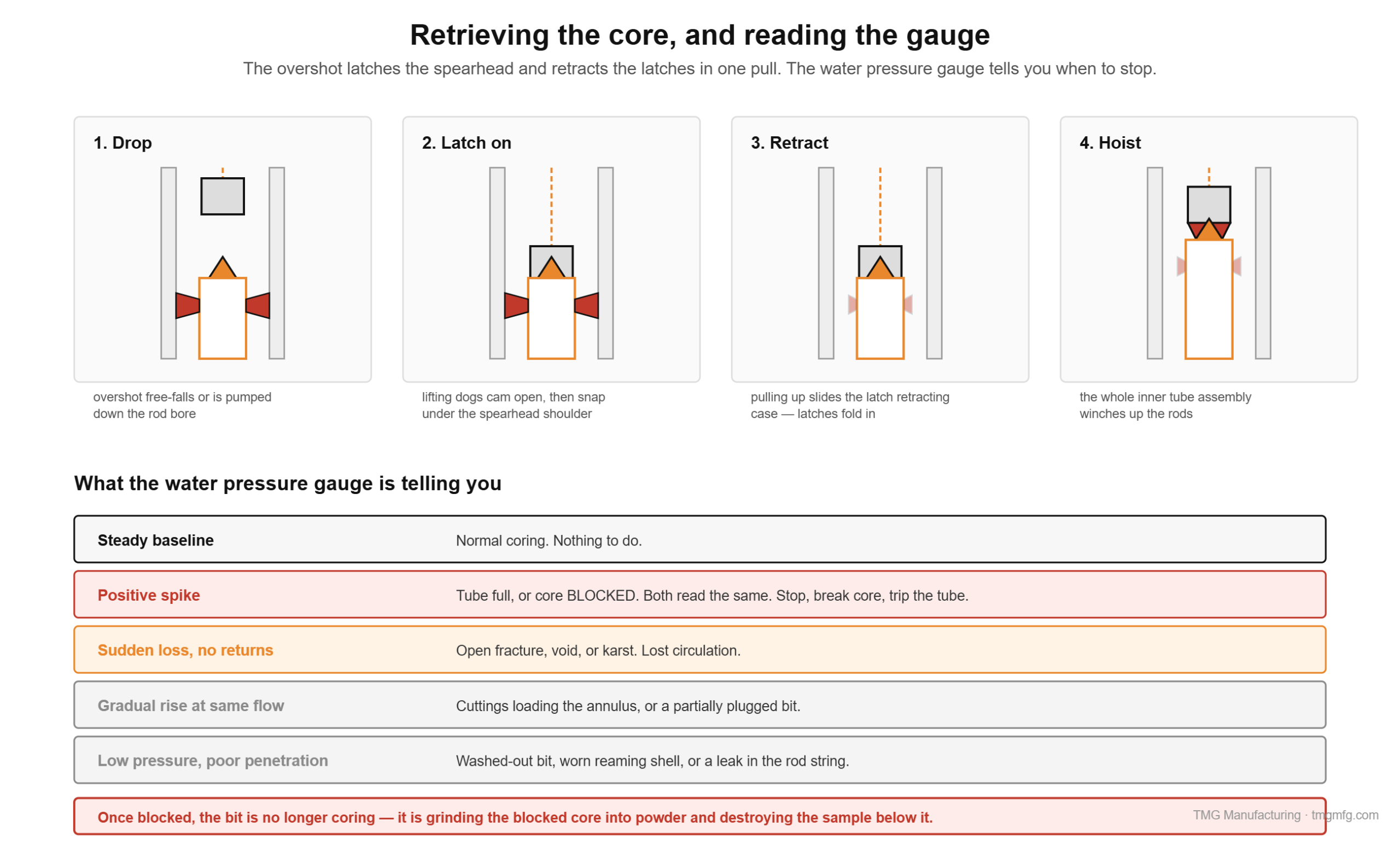
- Trip the inner tube. Break off the water swivel and drop the overshot on the wireline cable — free-fall in a shallow hole, pumped in on a deep or angled one.
- Latch on. The overshot’s spring-loaded lifting dogs snap over the spearhead point.
- Retract the latches. Pulling up slides the latch retracting case, camming the latches inward and out of the locking coupling.
- Hoist the inner tube assembly up the rod bore.
- Empty and re-run. Drop the empty tube back down, it lands on the landing ring, the latches spring back out, and the next run starts.
Anatomy: the outer assembly
Everything here rotates.
| Component | What it does |
|---|---|
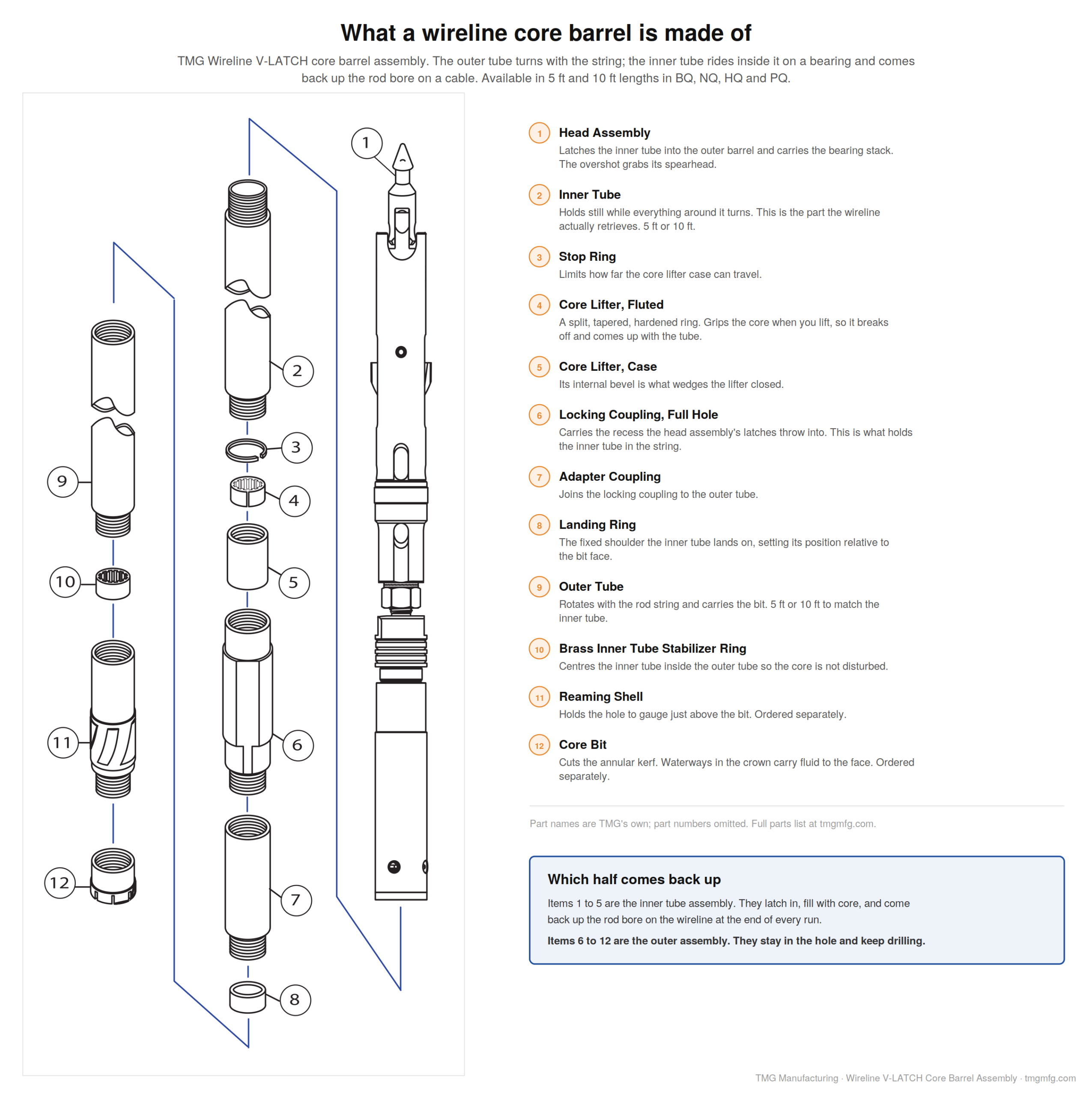
| Core bit | Cuts the annular kerf. Waterways in the crown carry fluid to the face. |
| Reaming shell | Sits behind the bit, diamond- or carbide-set on the outside. Maintains hole gauge so the bit isn’t the only thing holding size, and stabilizes it. A worn reaming shell means an undersized hole and eventually a stuck string. |
| Outer tube | The rotating body. Standard 5 or 10 ft. |
| Locking coupling | Threaded in above the outer tube, machined with an internal recess — this is the seat the latches engage. |
| Landing ring | Fixed shoulder inside the outer tube. The inner tube lands on it, setting its position relative to the bit. |
Anatomy: the inner tube and head assembly
This is the part most explanations skip. Manufacturers stack these in slightly different orders, so treat it as the parts list rather than a strict top-to-bottom section:
- Spearhead point — hardened and pointed, the feature the overshot grabs. It pivots, so the assembly can be swung 90° coming out of the mast.
- Latch retracting case — the sleeve over the latch mechanism. Pulling up on the spearhead slides it and retracts the latches. This is the release.
- Latches — spring-loaded arms that throw outward into the locking coupling’s recess. Original pivoting latches were 5/16 in thick; later designs doubled that, and current roller-type latches trade pivots for self-locking rollers.
- Landing indicator bushing and ball — a ball seated in a nylon bushing. As the tube lands and the string fills with water, pressure builds until the ball is forced through the bushing. That spike on the surface gauge is the driller’s confirmation that the inner tube has seated and latched, before coring starts. It is a landing signal. Do not confuse it with the check valve, which is a separate one-way valve down in the inner tube’s bottom C-cap.
- Landing shoulder — seats on the outer tube’s landing ring, stopping downward travel.
- Water ports — let drilling fluid bypass the landing ring and continue down to the bit face. Without them, landing the tube would deadhead the pump.
- Shut-off valves — rubber or nylon discs. When core fills or jams, they compress axially, expand radially against the outer tube, and choke the bypass — producing the pressure spike that ends a run. Valve hardness is selected for the ground: softer in soft formations where core loss is the risk, harder in competent rock.
- Compression spring — compresses on lift-off so the core lifter case can bear on the bit and transfer the load that breaks the core.
Then the inner tube itself, the core lifter — a split, tapered, hardened ring — and its case, whose internal bevel does the wedging.
The bearing is the whole idea
The outer tube turns — a few hundred rpm on the large sizes, faster on the small ones, and always faster than anything you would want a rock core subjected to. Inside it is a fragile cylinder of rock, sometimes broken into loose pieces, sometimes weathered and clay-rich.
If the inner tube turned with it, the core would be ground and twisted apart. That is exactly why single-tube barrels are limited to massive, hard, homogeneous rock.
The swivel-type double tube solves it with a bearing stack in the head: a spindle shaft connecting the rotating upper half to the stationary lower half, a thrust bearing taking the axial load, and a spindle bushing giving radial support.
The consequence is worth stating plainly: the rotating outer tube never drives the core in torsion. The core is pushed straight up into a tube that isn’t turning. It still sees bending and vibration, and it still gets loaded axially when you break it off at the end of a run — but it is not being wrung.
The maintenance implication follows directly. Grease the thrust bearing, spindle bushing and hanger bearing after each retrieval. A seized bearing turns a swivel barrel into a rigid one instantly, and the first symptom is a run of ground-up core.
Double tube or triple tube
| Double tube | Triple tube (NQ3, HQ3, PQ3) | |
|---|---|---|
| Construction | Outer + swivel-mounted inner tube | Same, plus a split liner inside the inner tube |
| Core size | Full for the hole | Smaller — the liner costs you diameter |
| Extraction | Pumped or tapped out of the inner tube | Split tube withdrawn and opened like a clamshell |
| Use when | Competent, intact rock | Broken, weathered, weak, or structurally sensitive rock |
For geotechnical work this is close to a settled question. USBR’s core logging guidance is blunt: split-tube core barrels should be used. The reason is not core quality for its own sake — it is that a fracture created while ramming core out of a plain inner tube is indistinguishable from a natural one on the log, and it silently depresses RQD. If the deliverable is an accurate fracture log, triple tube is effectively mandatory in anything but massive rock.
The cost is diameter. HQ gives 63.5 mm of core; HQ3 in the same hole gives 61.1 mm. And both NQ sizes — 47.6 mm plain, 45.1 mm for NQ3 — are already below the 54 mm generally wanted for unconfined compression specimens — worth checking before you commit to a size.
The overshot
A hoisting plug and cable swivel at the top, an overshot body that guides the tool over the spearhead, spring-loaded lifting dogs that snap closed beneath the spearhead’s shoulder, a dog case the operator squeezes to release, a safety pin, and on deep or angled holes a pump-in adapter so circulating fluid can push the tool down when gravity won’t.
Worth knowing as a safety matter: the spearhead is a single point of failure carrying a core-loaded inner tube over the driller’s head, and the lifting dogs grip the spearhead rather than the tube. Inspect spearheads, and do not stand under a rising overshot. That exposure is why modern designs market so heavily around positive locking.
Reading the water gauge
Three signals, all on the surface pressure gauge, and knowing which is which matters:
Tube landed — start of the run. Pressure builds as the string fills, then spikes as the landing indicator ball is forced through its nylon bushing. This one you want, and it comes before you core.
Tube full or core blocked — end of the run, one way or the other. Here is the part most write-ups get wrong: these are not two mechanisms. A full tube and a jammed core both compress the shut-off valve discs, which expand radially against the outer tube and choke the bypass flow. Same signal, and the gauge cannot tell you which. That is exactly why the response to it is the same either way — stop, break core, and trip the tube. If you were near a full run length, it was full. If you were three feet in, it blocked.
Once blocked, the bit is no longer coring — it is grinding the blocked core into powder and destroying the sample below it. Continuing past a block signal is the single most common cause of catastrophic recovery loss on a run. Stop, break core, trip the tube.
One caution: the signal is only as good as the shut-off valve. Worn or wrongly specified valves give no signal at all, and you find out at surface.
Other readings worth knowing:
- Sudden pressure loss with lost returns — an open fracture, void, or karst.
- Gradually rising pressure at constant flow — cuttings loading the annulus, or a partially plugged bit.
- Low pressure with poor penetration — washed-out bit, worn reaming shell, or a leak in the rod string.
Sizes: NQ, HQ, PQ — and the NWL question
The letter conventions come from DCDMA. The first letter is the size family, smallest to largest: R, E, A, B, N, H, P. The second is the series — X is flush-coupled (box thread at both ends, joined by a pin-to-pin coupling, thinner wall), W is flush-jointed (integral pin and box, heavier wall). WL means wireline. Q is not a DCDMA letter at all: it is one manufacturer’s proprietary system designation from the 1950s, a brand name that became the whole industry’s vocabulary. A numeric 3 means triple tube.
| Size | Core diameter | Hole diameter | Rod OD / ID | Rod weight |
|---|---|---|---|---|
| BQ | 1.433 in / 36.4 mm | 2.345 in / 59.6 mm | 2.19 / 1.81 in | ~40 lb per 10 ft |
| NQ | 1.875 in / 47.6 mm | 2.965 in / 75.3 mm | 2.75 / 2.38 in | 52.4 lb per 10 ft |
| NQ3 | 1.78 in / 45.1 mm | 2.965 in / 75.3 mm | — | — |
| HQ | 2.500 in / 63.5 mm | 3.763 in / 95.6 mm | 3.50 / 3.06 in | 76.9 lb per 10 ft |
| HQ3 | 2.41 in / 61.1 mm | 3.763 in / 95.6 mm | — | — |
| PQ | 3.345 in / 85.0 mm | 4.805 in / 122.0 mm | 4.50 / 4.00 in | 117.0 lb per 10 ft |
| PQ3 | 3.27 in / 83.1 mm | 4.805 in / 122.0 mm | — | — |
Now the NWL question, because the common answer is half wrong.
In current commercial practice, NWL is normally a synonym for NQ — distributors use the terms interchangeably in the same catalog, and most manufacturers outside that original line use the WL suffix for what are NQ dimensions.
But NXWL is not NQ. ASTM’s own tables listed them as separate rows with different numbers: NXWL cuts a 2.000 in core, NQ cuts 1.875 in. At H size the difference is larger still — HXWL cuts 61.0 mm core in a 92.7 mm hole, HQ cuts 63.5 mm in a 96.3 mm hole. (That HQ hole figure is ASTM’s; the major manufacturer catalogs publish 95.6 mm for the same size, which is the number in our table above. Manufacturers differ by a few tenths of a millimetre, and ASTM’s own footnote says so.) Different holes entirely. Not interchangeable.
The reason there are two vocabularies is trademark and lineage, not engineering. One maker got there first, so Q dimensions became the de facto standard and everyone else labeled theirs WL. The safe procedure is unchanged: check the specific manufacturer’s dimension table before mixing tooling. ASTM said as much itself — wireline dimensions and designations vary by manufacturer.
Rod weight matters more than people expect. A 1,000 ft NQ string is roughly 5,200 lb of steel before you add the barrel; at HQ it is 7,700 lb. That is hoist capacity, mast rating, and rig weight, and it is why size selection is a rig decision as much as a geology decision.
Water flow and pressure
Clear water is the standard fluid for geotechnical rock coring. Mud can be used for hole stability, but it clogs open joints and fractures — which invalidates permeability testing and piezometer installation. On a mineral hole nobody minds. On a geotechnical hole that will be packer-tested, it can void the investigation.
Published flow recommendations vary by source. A defensible range:
| Size | Flow |
|---|---|
| BQ | 20–30 L/min (5–8 gpm) |
| NQ | 35–50 L/min (9–13 gpm) |
| HQ | 50–70 L/min (13–18 gpm) |
| PQ | 80–100 L/min (21–26 gpm) |
Here is the rule hiding under that table. Work out the annular area for each size — hole diameter minus rod diameter, and remember that on a wireline string that gap is only about an eighth of an inch on a side — then divide the recommended flow by it. The low end of every size lands within a few percent of the same uphole velocity:
| Annulus | Low end | High end | |
|---|---|---|---|
| BQ | 0.55 in² | 184 ft/min | 276 |
| NQ | 0.97 in² | 184 ft/min | 263 |
| HQ | 1.50 in² | 170 ft/min | 237 |
| PQ | 2.23 in² | 183 ft/min | 228 |
You are not pumping 35 L/min because it is NQ. You are pumping whatever lifts cuttings at roughly 170 to 185 feet per minute, and the published tables are that one number translated into four rod sizes. Those velocities are high compared with what a mud rotary hand expects, and the reason is the annulus: a wireline string barely leaves room for the fluid to get past. (Annulus areas and velocities are our own arithmetic from published hole and rod dimensions.)
Pump pressure is not a spec — it is a consequence. No standard specifies a coring pressure. It is whatever the system needs to push the target flow through the rod bore, the bit waterways, and back up the annulus at a given depth. It rises with depth, viscosity, reduced clearance, and a blocked core.
Flow and recovery have a two-sided optimum. Too little and the bit overheats and glazes while cuttings recirculate and grind the core. Too much and the jet erodes soft, weathered, or fractured core at the face before it enters the tube — and that disproportionately destroys the weak zones that matter most geotechnically. Higher flow in soft fractured rock to clear cuttings; lower flow in hard competent rock to prevent polishing.
Handling the core
Run length: 3 m maximum, reduced to 1.5 m or less just below the rock surface and in highly fractured or weathered zones. Shorter runs in bad ground is the cheapest recovery improvement available.
Core goes into the box left to right, top to bottom — reading like a book. Use spacer blocks to mark run boundaries, and represent core loss physically with a spacer of equal length. Letting recovered core close the gap silently fabricates depth accuracy.
Mark mechanical breaks so the logger can tell them from natural ones. FHWA specifies three short parallel lines across the fracture trace. USBR’s field manual asks only that a line be drawn across the core to denote a mechanical break, without prescribing a form. Neither is universal, and neither is enforceable across a project by itself — so the actual professional requirement is that the project’s logging procedure defines a convention and everyone applies it.
Bit selection, briefly
Surface-set, impregnated diamond, or PDC. The governing rule of thumb is inverse: soft matrix for hard rock, hard matrix for soft rock — the matrix has to erode fast enough to keep exposing fresh diamond, and abrasive soft formations wear a soft matrix away before the diamonds are used. Waterway design controls cooling and cuttings clearance at the face. We’ll give bit selection its own post.
The standards problem nobody is talking about
This is worth knowing before you write your next specification.
ASTM D2113, the rock core drilling standard, was withdrawn in January 2023 with no replacement. ASTM D6032, the RQD standard, was withdrawn in 2026, also with no replacement. Reinstatement work items are open on both, but as of today:
There is no active ASTM standard for rock core drilling, and no active ASTM standard for RQD.
Anyone writing “core in accordance with ASTM D2113” is citing a withdrawn document. One live alternative exists for the drilling itself: AASHTO T 225, Diamond Core Drilling for Site Investigation. For field logging, ASTM D5434-25. Be careful with ASTM D6286 — it turns up on substitution lists, but it is a guide for selecting drilling methods, not a method. You cannot core to it any more than you can core to a catalog. That last one has an encouraging history: D5434 was itself withdrawn in 2021 and reinstated in 2025, which is the precedent the D2113 and D6032 reinstatement efforts are following.
One casualty worth noting: D2113 carried a recovery threshold — stop core drilling when recovery of the solid portion equals or falls below 50%, or whatever percent recovery level is unacceptable to the project — and adjust RPM, feed pressure, fluid flow, or barrel and bit type when recovery drops below 100%. The 2014 revision deliberately softened that from an absolute rule to a project-defined one. That guidance left the active standards library when the standard was withdrawn. It is still good practice. It just no longer has a document behind it.
Specifying a coring program or looking at rigs? TMG builds SPT and coring rigs and supplies wireline systems including large-diameter Geobor tooling — and we repair hydraulic drill rigs regardless of who built them. Call (813) 464-2299, toll-free 1-888-508-RIGS, or email info@tmgmfg.com.
Ramzy Moumneh, TMG Manufacturing — Tampa, Florida. TMG builds geotechnical drill rigs and deep foundation products.
FAQ
What is wireline core drilling? A coring method where the inner tube holding the core is retrieved on a cable through the drill rod bore, using an overshot, without tripping the rod string. The rods stay in the hole; only the core comes out.
What is the difference between NQ and NWL? In current practice they are used interchangeably — most NWL tooling is built to NQ dimensions. NXWL is a genuinely different size, cutting a 2.000-inch core against NQ’s 1.875-inch. Always check the manufacturer’s dimension table before mixing tooling.
When should you use a triple tube core barrel? Whenever the rock is broken, weathered, weak, or structurally sensitive — and effectively always for geotechnical work where the deliverable is a fracture log. The split liner lets core be removed without sliding it along a tube, which prevents drilling-induced fractures that are indistinguishable from natural ones on the log.
How do you know the core barrel is full? A pressure spike on the surface water gauge. Both a full tube and a blocked core compress the shut-off valve discs, which expand against the outer tube and choke the bypass flow — the same signal from either cause. (A separate, earlier spike, from the landing indicator ball passing through its nylon bushing, tells you the tube landed and latched at the start of the run.) The gauge cannot distinguish full from blocked, so the response is the same: stop, break core, trip the tube.
Is ASTM D2113 still current? No. ASTM D2113 was withdrawn in January 2023 with no replacement, and ASTM D6032 for RQD was withdrawn in 2026. Reinstatement efforts are underway. In the meantime, AASHTO T 225 is the live alternative for the drilling and ASTM D5434-25 for field logging. ASTM D6286 is sometimes offered as a substitute but is a method-selection guide, not a drilling procedure.
Sources
- ASTM D2113-14, Rock Core Drilling and Sampling of Rock for Site Exploration — withdrawn January 2023, no replacement
- ASTM D6032/D6032M-17, Determining Rock Quality Designation (RQD) — withdrawn 2026, no replacement
- ASTM D5434-25, Field Logging of Subsurface Explorations of Soil and Rock (withdrawn 2021, reinstated 2025)
- AASHTO T 225-16 (2020), Diamond Core Drilling for Site Investigation; ASTM D6286/D6286M-20 (selection guide, not a method)
- FHWA, Subsurface Investigations / Drilling and Sampling of Soil and Rock
- USBR Engineering Geology Field Manual, core logging and handling chapters
- Manufacturer diamond-products and coring-rod catalogs; published core barrel head assembly technical documentation
- Drilling-fluid product literature and published bit-wear guidance
Leave a Reply